|
|
Production
|
CNC Routers
Our Goal is to
provide the small manufacturer with the technology they need to stay
competitive at a price they can afford. Our machines are available as
total turn-key solutions, including everything necessary to successfully
operate the machine. Our machine is also customizable depending on
the application, here on this page are just a few of the many possible
configurations. Click Pictures with blue frames for more information
|
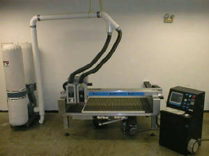
60"x48" Primary Head (7 HP)
|
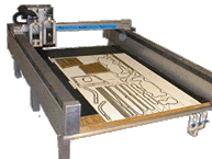
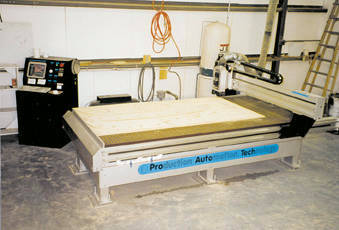
60"x120" Primary Head
|
|
|
Construction- Heavy Duty rectangular aluminum bridge and rails, Stepper motor powered, rack and pinion driven with cross shaft on Y-Axis |
|
|
Performance- Speeds up to 600 Inches per Minute, at a Resolution of 0.001", Full 3 Axis 3 Dimensional capabilities |
|
|
Routers- Router Sizes from 1.5 HP to 9 HP, or use a 1/2 HP Drill motor on one head |
|
|
Work Size- Two Standard Sizes available: 60" x 48" or 60" x 120" with 6" of Z Clearance, Table can be made longer (up to 24') or shorter depending on requirement and space availability |
|
|
Work Hold Down- Deck can be drilled and tapped or T-Slotted for mechanical jigs and fixtures, or milled into a vacuum grid for vacuum hold down, with various vacuum pumps or regenerative blowers ranging from 3HP to 20 HP |
|
|
Dust Collection- Standard with a dual bag, 1800 CFM 3HP Dust collector, can also be supplied with a single bag 1100 CFM 2 HP unit if one head is a drill, or with no dust collector to allow connection to existing, in-house dust collection systems |
|
|
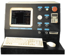
Control Cabinet- All controls for computer, routers, vacuum pump, dust collection, and emergency stop are centralized in a fan cooled and pressurized dust resistant enclosure. |
|
60"x120" Both Heads |
Series MCA |
|
|
Construction- Heavy Duty rectangular aluminum bridge and rails, Stepper motor or AC brushless servo powered, Lead screw driven with 2 matched Y-Axis lead screws |
|
|
Performance- Speeds up to 600 Inches per Minute, at a Resolution of 0.001", Full 3 Axis 3 Dimensional capabilities |
|
|
Routers- Router Sizes from 1.5 HP to 9 HP, or use a 1/2 HP Drill motor on one head |
|
|
Work Size- 60" x 120" with 6" of Z Clearance, Heads cam be spaced from 10" to 30" in 1" increments |
|
|
Work Hold Down- Deck can be drilled and tapped or T-Slotted for mechanical jigs and fixtures, or milled into a vacuum grid for vacuum hold down, with various vacuum pumps or regenerative blowers ranging from 3HP to 20 HP |
|
|
Dust Collection- Standard with a dual bag, 1800 CFM 3HP Dust collector, can also be supplied with a single bag 1100 CFM 2 HP unit if one head is a drill, or with no dust collector to allow connection to existing, in-house dust collection systems |
|
|
Control Cabinet- All controls for computer, routers, vacuum pump, dust collection, and emergency stop are centralized in a fan cooled and pressurized dust resistant enclosure. |
Head Configurations
Here are a few examples for head
configurations. Both the AFS and MCA Series CNC Machines can use the same
type of heads, and the possibilities are not limited to those configurations
shown. Air cylinder controlled slave heads are also available. Click
pictures for larger versions, or click HEREfor large versions of all 4 plus extra descriptions.
|
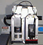
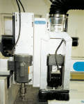
3.25 HP Porter Cable with |
1/2 HP Drill motor |
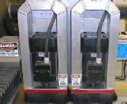
Two 7 HP Perske Spindles |
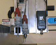
Two Milwaukee Drills set up as a Drill and Tap Head
with |
Control Cabinet
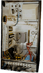
Here is what our control cabinet
looks like, inside and out. There is a 60 AMP Main breaker accessible
from the outside of the cabinet with a lockout facility available, each
circuit is also individually fused with industrial fuses, all contactors are
dust resistant for long contact life, all wiring is routed neatly in harnesses
for trouble free operation. Cool air is brought in from near the floor
through a heavy duty filter by a 560 CFM 10" fan, the cool air coming in
low is then used by the electronics with their own fans and the hot air is
directed away from the cool intake, the warm air (which rises) is
exhausted through a 4" vent up near the top, this lets an incredible
amount of warm air out of the cabinet, but even with a 4" vent, the
10" fan can still put more air in, the result is a pressurized cabinet
with good airflow, with the inside pressurized, any gaps (such as the door in
the floppy drive) have air coming out... and if air is coming out, dust can't
get in. The system is also pre wired for automatic head power with
program control, and optional (via the front panel switch) dust collector and
vacuum pump automatic power. Click Picture for larger version.
|
Inside AFS Control Cabinet with one 7 HP Perske and one 3.25 HP Porter Cable |
Front of control cabinet with obvious emergency stop, all switches and vacuum gauge in convenient locations. |
Vacuum Pump Options
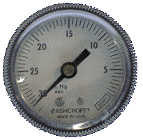
Vacuum Tables are standard on AFS
and MCA Series machines, as well as a Vacuum Pump. The Size and style of
pump depends on the type of parts that are to be cut. The Vacuum
hold down method works by removing the air out from under your parts, it is
then the effective weight of the atmosphere (or the difference in pressure
above and below the part) which holds the parts down. Vacuum is usually
expressed in inches of mercury (in.Hg), a 30 being about the highest you can
get on planet earth at sea level (above is an actual control cabinet gauge
photograph, at our shop in Clearwater, FL). A 30 basically means you have
removed absolutely all the air and you are measuring the barometric
pressure. Many factors affect the actual pressure you can achieve, such
as altitude, if you are 5000 feet above sea level, you will never get more that
25 in.Hg. however if you were to go to Jupiter, where the atmosphere is
very thick and dense, you may 1000 :) anyway back to earth and your
parts. You can convert inches of mercury readings to PSI (Pounds
per Square Inch) approximately, by dividing the Inches of mercury reading by
2. So if you are in Florida (Mostly very little above sea level) and you
are reading 30 in.Hg, you could say you had around 15 PSI holding down your
part. Now, Say you had a part that was a 12" square... to find the
total area, you multiply the length times the width, so you would have 12x12=
144 Square inches... next, you would say hmmm 144 square inches with 15
pounds pushing on each one, that would be 2160 pounds!!!! Now routing with
a 3 HP Router takes about 20 pounds of pressure... That part is NOT going to
move! where the problem is, is in small parts... if you had a 1"
square.... times 15 Pounds per square inch ... you would have one square inch
with the 15 pounds on it..... well this part may move if you try to cut too
fast. When selecting a vacuum pump, you must also consider air flow
capacity... you may have small leaks around gaskets or even through the
surface of your parts, your pump needs to be able to keep up with these
leaks, and remove the air faster than it can leak in.
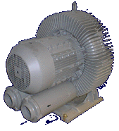
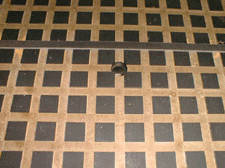
Regenerative blowers as shown at left, above, (Click on picture for larger size) have very large air flow capacities, meaning they move a very large volume of air at a high speed, but they usually cannot draw very much pressure, this type of pump is used where parts are fairly large in size or pourous, where air can get through the parts, such as particle board or MDF. They can also be used in through vacuum applications, where the user lays down a piece of particle board on the vacuum deck (right picture shown) and then puts the parts directly on top of this. To Seal the particle board "Spoil board" to the vacuum deck, a gasket is installed in the groove all the way around the spoil board. In this type of system, the pump draws air through the gaps in the particle board and holds the parts down to it. these types of pumps usually can only create a maximum of 11 in.Hg, or about 5 pounds per square inch, so they will only be effective for larger size parts, generally over 20 square inches.
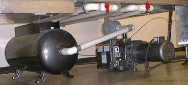
Rotary Vane Vacuum Pumps as show at left, above, (Click on picture for larger size) Can draw a very high vacuum, however they are much lower volume than a regenerative blower. This type of pump can be uses for very small parts as well as large parts, and very large rotary vane pumps can be used in through vacuuming applications as described above. The most popular method oh holding parts down with a rotary vane vacuum pump, is to create a "spoil board" for your part. this procedure, you would place a non-pourous board on the vacuum deck, something like melamine board, or plywood that has been painted also would work. Then you run your program and cut say 1/32" into the board. Then you would apply self adhesive gasketing around the inside of the cut, see example on right above. Next you would drill a few holes (around 1/4" works well) inside the gasket and through the spoil board, into the vacuum grid. Now when you put your material on top of this, you have rubber seals preventing the air from leaking, and your pump can remove all the air out from under the material, usually providing you with over 25 in.Hg, or 12 Pounds per square inch. This type of pump is usually used with a "Surge Tank" shown to the left of the pump above. When the valves are closed, the pump removes all the air from the tank, then when the valves are opened, you have a very large inrush, much faster than the pump can produce, this will help pull down warped sheets. After the parts are held down, and the pump is keeping up with the leaks, the tank just has the air passing though it, with no real affect on the system. For more information various methods of vacuum hold down techniques, please visit our Jigs and Fixtures Page.
|
|

